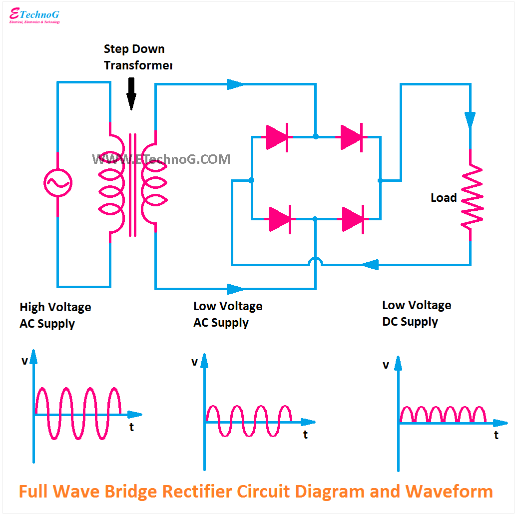
Introduction Of Full Wave Rectifier
Half wave rectifier – definition, working, circuit diagram, theory Rectifier wave bridge full operation half animation working input cycle positive current forward during gif diodes reverse biased d3 d4 Full wave rectifier by jayasri.k(221710303019)
Half Wave Rectifier – Definition, Working, Circuit Diagram, Theory
Rectifier wave full bridge piv voltage peak inverse engineeringtutorial half output engineering tutorial Full wave bridge rectifier circuit diagram Full-wave rectifier
Rectifier control diodes thyristors constructed devices place
Rectifier working tapped animation voltage rectified circuits cycles engineeringtutorial biased consists thus independently eachRectifier waveform Diode circuits preciseFull wave and half rectifier model hindi youtube.
반파정류기와 전파정류기를 이용한 캐패시터 필터-전자-fmuser fm/tv 방송 원스톱 공급Rectifier transformer tapped output input waveform What is full wave rectifier ?Full wave rectifier schematic.

Rectifier tapped operation
Rectifier disadvantages advantages electronicscoachCenter-tapped full-wave rectifier operation Precise diode circuits : worksheetComparison of half wave rectifiers and full wave rectifiers.
Full wave bridge rectifier operationRectifier circuit Full wave rectifier schematicWave half rectifier diode ac voltage supply output circuit peak inverse dc piv operation value load input average when resistance.

Full wave rectifier schematic
Half wave rectifierMake three phase full wave rectifier circuit. Rectifier wave half positive engineering stackFull wave rectifier circuit working and theory.
What is full wave rectifier, types, woking, rms, operation, pivRectifier circuit diagram Introduction of full wave rectifierWhat is full wave rectifier circuit diagram working advantages.

Full wave bridge rectifier peak inverse voltage
Rectifier circuit diagramWave half full comparison rectifiers vs rectifier bridge articles related transformer engineeringtutorial .
.


.jpg)

